AMforum Journal 1
Testing DRM with Series Transformer
Transformers equipped with a series transformer
- or a booster transformer, to minimize the current OLTC switches during the tap
changing process are explained in this document.
DEFINITION : Series transformer
In certain parts of the world, OLTC is located
in the low voltage (Secondary) winding of a power transformer, like the USA,
while the other parts of the world put the OLTC in the HV winding, typically in
Europe.
Since the current of the LV winding is higher
than the HV winding current, OLTCs located in the LV windings have to switch
higher currents. To lower this current, a series transformer is introduced.
The Waukesha Electric System (WES) states:
•"The WES
LTC may utilize a series
(booster)
•transformer that is
built of circular coils and cruciform
•stacked core
construction, when the low voltage current
•exceeds the LTC
current rating. A series transformer is
•used to “boost”
voltage and reduce the current applied
•to the LTC contacts.
This series transformer is equal in
•size to the full
percent regulation. For example, a 50
•MVA power transformer
with +/-10% LTC regulation
•would have a 5 MVA
series transformer inside the main
•tank. The short
circuit withstand capability of this
•transformer is equal
to that of the main transformer. At
•WES, the series
transformer is built of the same
•construction as our
main power transformer core/coil assembly"
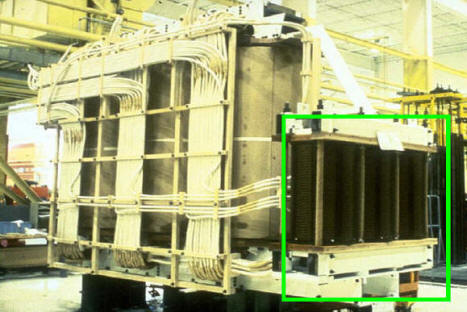
Fig.1. Photo of a power transformer with the Series transformer -
circled in green
Here is a portion of the nameplate showing this
arrangement. It is clear that there is no electrical contact between the
secondary winding (LV) and the regulating winding (RV) connected to the tap
changer. The only coupling is magnetically through the series transformer.
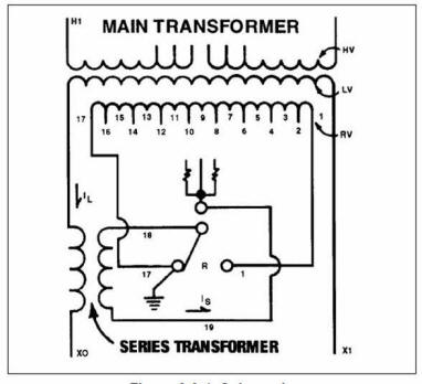
Fig.2. Portion of the transformer nameplate showing series transformer
TESTING
Testing DRM presents a special case and
requires a special procedure. One is developed following a proprietary algorithm
patented by DV Power.
Dynamic Resistance Measurement is a winding
resistance test current record during a tap change. Having this in mind, lets
discuss the winding resistance results. This is also known as a "static
resistance" or the Winding resistance results of the secondary winding does not
change as a tap position is being changed. This can be deduced visually
observing the schematic diagram of the nameplate, as no tap changer nor the
regulating winding are in the test circuit. To conclude - a graph of the static
resistance results for each tap position, should be a flat horizontal line.
Likewise, the DRM graph should also be a flat
diagram as shown on the figure below, because there is no resistance change.
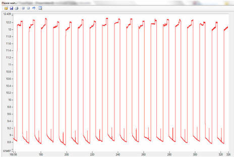
Fig.3. A flat DRM graph
Knowing all this, the analysis of the tap
changer transition is based on the ripple evaluation only. To see the ripple we
need to excite the series transformer winding in order to reflect the ripple of
its current on the current we measure - the test current through the secondary.
We have devised the procedure where a disturbance is introduced in the circuit
by sharply changing the test current. This change induces the voltage and
current in the regulating winding, since during the DC test there is no current
in other windings.
The graph below shows three motor operations
(green trace), i.e. three tap changing operations. As the excitation disturbance
is introduced immediately after the motor starts for the first time, the
reflection of the ripple during the first transition is visible, while the other
two are not.
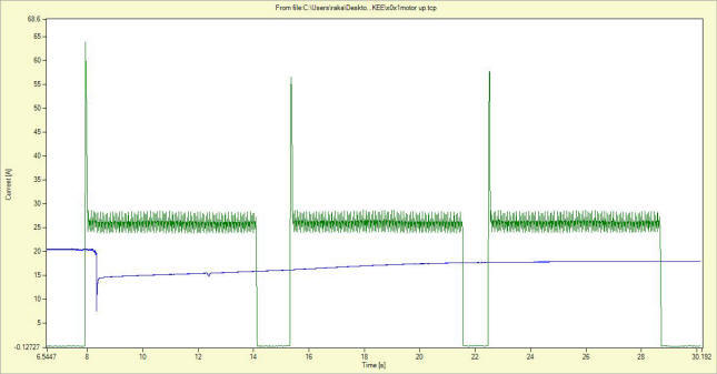
Fig.4. Three tap changing operations - only the first one shows the reflection
of the ripple
This reflection is the mirror image in the
opposite direction, i.e. a normal ripple may be a current drop, now the ripple
becomes a current "jump".
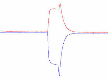
Fig.5. Ripple in blue, and reflection trace in red.
ANALYSIS
The analysis of the DRM graph can be performed
by checking transition times of each tap changing operation. The transition time
comprises of three segments – resistor 1 in the circuit, resistors 1 and 2 in
the circuit, and the last one – resistor 2 in the circuit, before the main
contacts make, as observed on the DRM graph as an exponential raise, where the
current goes into recovery.
Any discrepancy in the ripple value may
indicate a potential problem. However, we have seen that the ripple changes from
tap to tap position, or even changes its direction (we will write about this in
the next issue of Journal) and depending on the parameters of the test circuit
may hinder this evaluation.
Contributor
Dr.ing. Raka Levi