AMforum Journal 4
Power Transformer Magnetic Core Demagnetization
MAGNETIZATION
A magnetic core of power transformers is found
very often in a magnetized state. This magnetism is called remanent magnetism,
and it has undesirable effects on transformer operation. Several reasons cause
remanent magnetism:
1. When disconnecting a transformer from
service. Since the current is never in phase with the current, and the
current is interrupted at point zero - there is certain voltage at
that point, and corresponding flux would remain in the core at that
point
2. Consequence of high fault currents that
a transformer withstand, where relays cleared the fault leaving some
magnetism in the transformer core.
3. Testing using DC current, most common
is winding resistance test. As a DC current is used to measure the
resistance of transformer windings, once the transformer is
discharged after the measurement, the core remains magnetized.
4. Lachman in his paper [1] concludes that point of minimum energy that
magnetic core tends to obtain over time is not the point of zero
magnetism, which means that if the transformer is idle for a prolonged
time period, the magnetic dipoles may orient themselves in a way that
the energy is minimum and at the same time the flux is not. In analyzing
the data influenced by the transformer magnetic circuit, it is often
assumed that the core would remain indefinitely in the state it occupied
at one point, unless modified by electrical excitation. This assumption
was challenged when changes in the low-frequency range of the frequency
response were observed with no electrical excitation applied between the
measurements.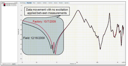
From
Lachman's paper [1] - Influence of Magnetic Viscosity on FRA graphs
EFFECTS
The remanent magnetism can cause various
problems:
-
high amplitude of inrush current at
start-up of power transformer,
-
incorrect operation of protective relays,
- the windings are exposed to mechanical
stresses that can damage the transformer
-
power-quality problems may arise: high
resonant harmonic overvoltages and voltage sags
- erroneous diagnostic electrical
measurements on a transformer:
-
- Frequency Response
Analysis Test graphs with resonant peaks at the wrong place [6],
-
- Excitation Current Test
showing incorrect pattern of current readings (pattern is used for
diagnostics)
Kovan et al. in their paper [2] conclude that
when the mitigation technique was used, the inrush currents calculated at the
head of the feeder were reduced by about 60%. The IEEE PC57.102 recommends
removing remanency before putting a power transformer back in service.
DEMAGNETIZATION
METHODS
Several methods of removing remanent magnetism
are described in the literature. The oldest ones back in 1960ties and 1970ties
were performed using car battery, creating a large arc as the cables were
disconnected from the transformer bushings. This method would demagnetize one
phase and magnetize the other phase of a three phase unit. Also, the arc would
be a scary event, that could cause an accident if not from the arc itself , then
by the fall from a transformer top. This method, most commonly used for
demagnetization of a transformer is based on the standard found in IEEE 62-1995
(section 6.1.3.5) (6) which directs one to alternate the polarity of a fixed
voltage with decreasing application time per alternation of polarity. With each
alternation, the voltage is applied until the current flow has reversed and is
“slightly lower” in absolute magnitude than the current in the previous
application. The time was used as a measure of the current magnitude, given the
car battery voltage is constant.
Makowski in his thesis [3] lists three methods:
Permeability Method, Time Based Method, and Integration Method. We will list
other methods as well:
A. Permeability Method was expected to be the
most direct and quickest demagnetization method since it only required the
voltage to be applied once for saturation and then reversed once for
demagnetization. However, its accuracy and effectiveness regarding
demagnetization is dependent on many assumptions about the properties
of the transformer.
B. Time based, where the magnetic flux is
directly proportional to the amount of time that a constant voltage is applied
to the winding, by measuring the time needed
for the magnetic state of the core to switch from being saturated in one
direction to becoming saturated in the opposite direction we can determine how
long a constant
voltage needs to be applied to the winding that is saturated in order to reach
the neutral point.
C. Integration method calculates the integral
of the voltage applied in time, and provides as a result the exact time required
to demagnetize the core applying reversed polarity.
D. The Controlled Current method is the
"engineering" approach to the IEEE standard directive to
alternate polarity and lower the flux in the magnetic core by controlling the
current amplitude in each step. The value of the initial amplitude is not
important as long the saturation is reached on all three legs of the magnetic
core. Following initial current charging and discharging, the next alteration is
of 60% magnitude and when reached, discharge is initiated and the steps go on in
succession until the very small value of Ampere-turns is applied as the very
last step.
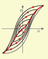
Demagnetization process explanation (left)
and test results recorded (right)E. In the paper by Kovan [2] a different
procedure from the Integration one explained under C above is given. The steps
to demagnetize a core are as follows:
1) Bring the core to saturation by applying a positive voltage. This step is
needed because the initial residual flux is not known. The indication that the
core has
reached (positive) saturation is when the current stops increasing.
2) Reverse the applied voltage (to negative ) and measure the time that it takes
for the core to be fully saturated in the reverse direction. The time to bring
the core from positive saturation to negative saturation is "T". According to
Faraday’s Law, the integral of the voltage from [+] to [-] gives a flux equal to
twice the saturation flux.
3) Reverse the voltage once again to apply positive Vdc . Theoretically, if we
apply the voltage for a time equal to "T"/2 starting from negative saturation ,
the core would be completely demagnetized.
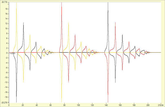
Demagnetization of 1100MVA transformer following
the Controlled current method
EVALUATING DEMAGNETIZATION SUCCESS
To verify that the demagnetization was
performed successfully, one has two options: to perform the FRA test and compare
the graph with the one obtained in the demagnetized state, or to perform the
single phase Excitation current measurement (Iex) and compare the values of test
current phase per phase to the known value. In case no known values are
available, looking at the Iex pattern and knowing the construction of the
magnetic core may be helpful.
The single phase excitation current values for a
demagnetized three phase transformer with three legged core form magnetic
circuit should compare between outer phases (A and C). When magnetized, these
currents measured at 10kV test voltage, can show over 25% difference [4].
Excitation current results at 100V test voltage for phases A - B - C,
after DC winding resistance testing on a three phase transformer:
•Iex (single phase) 17.2 -14.1 -14.2 [mA]
Results obtained following an initial 40A current demagnetization
using controlled current method:
•Iex (single phase) 8 - 6 - 8 [mA]
Two graphs are shown in figures below
obtained with FRA method, the one where the first peaks below 1 kHz are shifted
due to the remanent magnetism, and after the successful demagnetization the
peaks of the outer phases do coincide as expected.
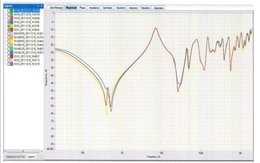
FRA traces of a 80 MVA transformer in magnetized state
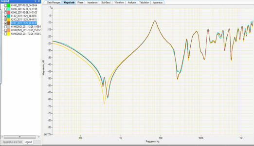
FRA traces after a successful transformer core demagnetization
CONCLUSION
There are effective ways to remove remanent
magnetism, even for the largest power transformers [5]. This will extend
transformer
life by simply avoiding large mechanical stress at a startup, and will provide
a more reliable test results when performing condition assessment using
various A.C. test methods.
REFERENCES
[1]
Frequency Response Analysis of Transformers and Influence of Magnetic Viscosity,
M.Lachman et al., Doble Conference 2010
[2] Mitigation of Inrush Currents in Network
Transformers by Reducing the Residual Flux With an Ultra-Low-Frequency Power
Source,
Baris Kovan, Francisco de León, Senior Member, IEEE, Dariusz Czarkowski, Member,
IEEE, Zivan Zabar, Senior Member, IEEE, and Leo Birenbaum, Senior Member, IEEE;
IEEE TRANSACTIONS ON POWER DELIVERY Paper no. TPWRD-00317-2010. Digital Object
Identifier 10.1109/TPWRD.2010.2102778
[3] Proposal and Analysis of Demagnetization
Methods of High Voltage Power System Transformers and Design of an Instrument to
Automate the Demagnetization Process, N.J. Makowski, Masters Thesis at Portland
State University 2011
[4] Condition Monitoring Unit (CMU), Asset
maintenance department report, TNB Malaysia, 2011
[5] H.
Kristensen,V. Mrdic, “Comparative analysis of three phase and single phase
dynamic resistance measurement results,” C I R E D 22nd International Conference
on Electricity Distribution Stockholm, June 2013, Paper 0473
[6] Report
of the CIGRE Working Group A2.26, Mechanical condition assessment of transformer
winding using Frequency Response Analysis (FRA)
Contributor:
Dr.ing. Raka Levi
Based on notes from a lecture given in Melbourne, Australia April 2013