prepared by R. Levi, based on evaluation collaboration with colleagues from GVEA and Doble.
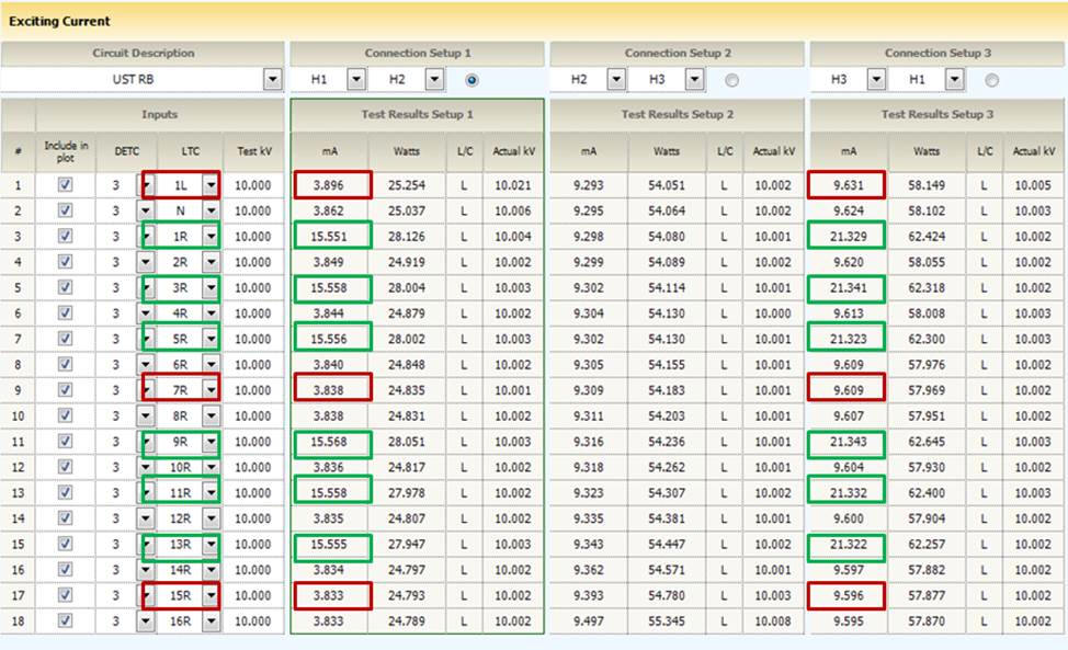
During the regular maintenance testing of a power transformer equipped with Westinghouse type UTTB tap changer, Doble excitation current results were found incorrect on several tap positions. For a reactor type OLTC the excitation current should alternate between high and low values as the tap changer goes through bridging and non-bridging positions. The bridging (odd) position Iex should be higher than the even (non-bridging) positions due to the PA inclusion in the test circuit.
The figure below shows the first and the third phase Iex results do not follow this pattern in positions 1L, 7R and 15R (in red squares). The middle phase mA values slightly increase with each position of tap changer without ever alternating high-low.
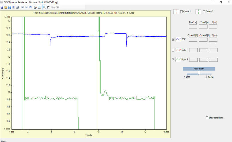
The dynamic DVtest was performed to evaluate the tap changer dynamic operation in order to find a cause of this problem. Two traces are recorded synchronously, the test current in blue and the motor current trace in green as shown in the graph below. The motor current shows a peak inrush current when the motor starts operation, then 4 seconds of steady operation, and then it stops with current dropping to zero.
A good reactor tap changer characteristic DVtest current trace shows two features per one transition: ripple when the contact opens, and another ripple when the contact makes with the next tap.
The figure below, recorded while the tap changer was operating in the "lowering" direction shows only one ripple during the first motor operation. This is the opening ripple, while the closing ripple is missing. Only after the motor operated for the second time the closing ripple is observed. Then there is another ripple, so this motor operation has two ripples but they are in the opposite order. The closing is first and the opening comes afterwards. This was a clear indication that the mechanical adjustment of the tap changer was wrong.
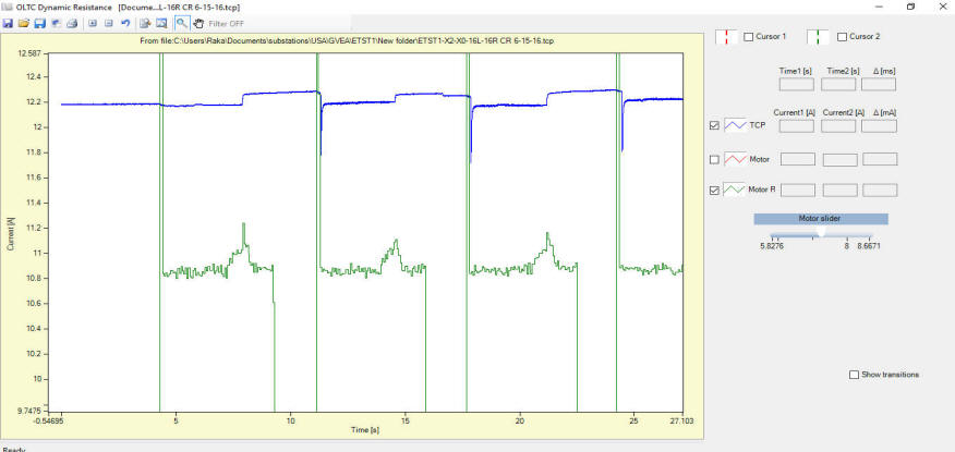
The figure below shows the trace recorded while the tap changer was operating in the other - "raising" direction. Here also the first motor operation shows only the closing ripple. The next motor operation shows two correct transition ripples, however the timing is not proper - the operation of switches starts too early in the motor sequence. The same for consequent operations.
Careful examination of the OLTC mechanism showed the cam switches that operate transfer switches were not adjusted properly. The maintenance crew findings are reported in the further text:
Conclusion:
a. The PA (preventive autotransformer) has not been switched-in completely during the OLTC operation. This led to incorrect excitation test results for bridging positions.
b. DVtest results correlated motor operation with switching sequence and detected transfer switches operational discrepancy. Without motor trace, this finding would have been impossible to detect.
Recommendation: The continuous test should always be performed recording the motor current as well. Both directions recording is a must. Alternatively, step by step test would indicate each transition boundaries, but for a reactor OLTC the motor trigger is recommended, thus - the motor trace should be present.