Abstract
Winding resistance of power transformer may take excessively long time to obtain stable results. Creating an instrument with two independent sources to charge primary winding and secondary winding separately will speed up this process. Special connecting arrangements provide for proper magnetic core saturation that makes stabilization of test results fast. Additional advantages of this arrangement are explained.
Introduction
Winding resistance measurement of a large transformer is a complex process. We deal with inductance of a transformer that was designed for AC operation, and we test it using a DC voltage and current. The inductance restricts current flow and creates three characteristic processes during the test: charging, stabilization, and discharging. Lets’ explain each one.
Charging is the process where a DC current is established through the winding, the time required for this process depends on the voltage rating of the transformer winding and applied DC test-voltage. It may be very long if testing using low voltage like 5-10V. Modern instruments apply 50-100V to speed–up this process. Our experience with 1000kV unit required 70 seconds for the charging process. Once the charging is done and the selected current is established, the stabilization starts. The time required for the current to stabilize depends on the L/R time constant.
Only when the test current is stable resistance can be
measured correctly. To minimize this time constant we saturate the magnetic core
using as high current as necessary to reach and exceed the knee-point on the
hysteresis curve. Of course, the test-current should not exceed 10% of the rated
current to avoid heating the winding. Stabilization can last even few hours for
some particular situations. The worst ones are
Discharging is the last process after the measurement results are obtained, and requires safe discharging circuit to automatically discharge the energy stored in the magnetic core. This energy is proportional to the square of the test current and the winding inductance. Discharging usually lasts the same amount of time as the charging process.
Applying current through both HV and
Instrument with only one source can perform this by
connecting HV and
Instrument
The instrument is equipped with test-lead connections for
Kelvin method of measurement for both HV and
Two powerful DC sources in the instrument are configured such that one has higher voltage with lower current output, and that one is used for the HV winding measurements, while the other source has lower voltage and higher current output.
Two sources can be started either at the same time or one
after another. Our field measurement proved that starting the HV winding
charging, followed by charging of the
The instrument is also equipped with powerful discharging circuit and a set of relays that may accomplish any of the test configurations and even reverse the polarity of the applied voltage, as required for the demagnetization process. Multitude of additional input channels are used for various signals that are required such as: temperature, motor current, vibration, or anything else.
Advantages:
There are several interesting advantages in applying two sources for transformer testing that allow for easier and faster test performance.
1. There is no
need to short the primary HV winding when testing the secondary winding only
(the
2. The dynamic testing can take advantage of BOTH
connections. While it is impractical to use saturation of the HV side when
dynamically testing the OLTC on the
3. For the QuickYN test, explained in the section “Connections” below, magnetic flux is forced by two sources the way we want it to split between core legs. Advantage over single source is much faster stabilization due to forced equalizing of flux through the three core legs, while the single source requires natural flux distribution and equilibration that may take long time.
4. Two different modes of testing can be performed on transformers with OLTC. One is winding resistance measurement at each tap position, the other is a dynamic recording. We call the dynamic one the DVtest used to verify an OLTC performance during the transition from tap to tap. These two modes can be achieved using two procedures.
One is called step by step and requires double number of steps compared to number of tap positions. Steps alternate between resistance measurements and dynamic recording. Following a resistance measurement on a position 1, the dynamic test would record a graph of transition between taps 1 and 2. These two steps are then repeated until all the positions are measured.
The other procedure is called the Continuous test. It is a faster test as the process records the entire time a dynamic graph as the tap changer switches between positions – form one extreme position to the other.
Connections
This section will deal with different winding configurations and vector groups. Also, specific test procedures for non-routine tests such as heat run or synchronization are examined.
a. Regular winding resistance testing can be performed
three ways: only the HV, only the
When testing only the HV side the process is straight
forward, while testing the
Charging with reduced voltage is another option that provides certain advantages, and makes charging process somewhat slower but may speed up the stabilization process. As lower charging voltage and the spike it creates when applied induces smaller effect in the other winding, this procedure is applied whenever problem of induced voltage being too high is detected.
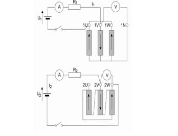
b. Heat run testing issues – following IEC or IEEE standards user can apply the standard or alternative procedure for heat run test. The standard procedure requires two sources to measure two hot spots at two windings, the HV and LV. The alternative one is using only one source. Connection of the standard procedure with two sources is shown in the figure below, as provided by the IEEE standard. The HV side is charged through the middle phase and the return is through the outer phases connected in parallel (for YN connection). The resistance is measured on the winding of the middle leg.
The
c. Synchronization test
Having several tap changers (2 or 3) on the same drive mechanism, would require verification of their synchronization. The current is injected in all three phases from one source. The test side is the one where the OLTC is located and the current will distribute through the phases in accordance with the ohmic resistance of the three phase windings. The flux induced in the core applying current through all three phases will have no return path, except in case of a five legged cores, and will return through the air as leakage flux. This automatically minimizes inductance and makes core saturated for a perfect dynamic graph recording.
d. The QuickYN test is a great time saving function for transformers with on load tap changers (OLTC). This method measures all the phase resistances at the same time. Having units with 33 positions will require 99 regular measurements. Using QuickYN procedure only 33 tests are performed, and 2/3 of the testing time is saved.
Connection can be established with one source or with both current sources. Using one source, current applied through the middle phase returns through the other two. Having neutral accessible in the star/wye connection (that is the reason for YN in the name QuickYN) provides measurement point to test the voltage drop on each phase winding.
The other option is applying two currents, one through each of the outer phases and returning through the middle one. Again, voltage measurement is obtained on all 3 phases using accessible neutral point. Having three voltages and three currents measured, the resistance of all three phase windings can be calculated. Advantage of the two sources is faster initial stabilization time.
e. Dynamic testing
Tap changers are positioned usually in the
f. Testing autotransformers
A special configuration of an autotransformer where HV and
g. Demagnetization can be performed from the HV or from the
Conclusion
Two sources instrument developed by DV Power solves many issues and provides several important benefits for a winding resistance static and dynamic testing.
Manuscript received on July 19, 2017 – final version accepted for publication TBD