AMforum Journal 1
Dynamic Resistance Measurement for On-Load Tap Changer Maintenance
By Ernesto Perez Moreno, Gas Natural Fenosa (Gas and Electricity Utility), Spain
* * *
On-Load Tap Changers (OLTC) require maintenance at regular intervals as specified by the manufacturer based on the number of tap-change operations. However, research by Hydro Quebec indicated that 12% of the OLTC’s in commission require corrective maintenance at more frequent intervals than the manufacturer’s recommended frequency. Therefore in order to optimize expenditure on the maintenance of OLTC’s utilities need to establish a strategy whereby condition assessment can be achieved using a reliable and simple tool.
Some 40% of all power transformer failures are attributed to the OLTC, the only moving component operating at high voltage. Early detection of an incipient problem before it leads into a catastrophic failure with possible environmental consequences is paramount. It can help the utility improve risk management, prioritize investment and maintenance decisions and influence the stakeholders’ management.
Dynamic Resistance Measurement
Dynamic Resistance Measurement (DRM) is an off-line test that usually takes an hour to perform on all the tap positions and on all three phases of a power transformer. The number of problems and defects that that DRM can identify are numerous. Based on the results it is possible to differentiate between the root cause which could be the selector switch or the diverter switch. This diagnosis is important as to repair the selector switch requires opening the main tank of the transformer whereas the diverter switch can be extracted and repaired. Burnt, coked, bouncing, corroded contacts of the selector switch, misalignment of the mechanical parts and malfunction of the diverter switch cause the regulating circuit to open during the transition, or arc under oil. This causes gas generation and possible Bucholz tripping. These are just some of the problems that an asset manager faces when dealing with OLTC faults.
The DRM test methodology has proved to be an excellent tool over the last 15 years in Europe, where the tap changers are of resistive type. Recently, the method has been successfully applied to the reactive tap changers in the USA. Furthermore, a special procedure was devised for tap changers with series transformer in the circuit.
Test Procedure and Instrumentation
Modern winding resistance test instruments use sophisticated power electronic circuitry to produce a smooth filtered DC current for transformer resistance measurement. This allows for interconnection and communication with the PC, thereby allowing fast sampling records of this measurement to be stored on the hard drive. Sampling rates of 4 millisecond or even 0.1milliseconds are common and provide a large file of test current profiles, with many details that can be analyzed using zoom functions.
In 1998 Gas Natural Fenosa (GNF) the Gas and Electricity utility in Spain, started to develop a system that was based on Hall Effect probes and conventional oscilloscopes. Following this, commercially available equipment for this purpose became available. The Swedish Company DV-Power provided (GNF) with their first design of a recording instrument several years ago, and by working together, they redefined the requirements for the RMO60TD tester, a powerful (60Amp) versatile model for this type of diagnostics. The letter D in the model stands for demagnetization – the new model comes with this feature as standard. Using USB connection, a Windows based program operates the instrument and records/displays the graphs.
During tap-changer operations each time the tap position changes, the current drops to certain value due to the introduction of circulating-current limiting-resistors in the circuit. This current drop is a feature known as the Ripple, and its value depends on the construction of transformer and OLTC, measuring circuit parameters, and test method (shorting secondary circuit or not).
Each current drop or Ripple can be analyzed by zooming into each transition portion of the recorded graph. Two red cursors indicate the beginning and the end of the transition, and the transition time is another useful feature extracted from the graph - a powerful tool in diagnosing diverter switch mechanism malfunctions. Depending on the voltage regulation an experienced engineer can diagnose problems with a particular component of the OLTC.
Problem identification
OLTC’s comprise two parts: the diverter switch, which diverts the current during the transition and minimizes arcing, and a tap selector which selects the tapped winding connection. There are, for certain designs, switch-over selectors or inverter switches, and also combined selector-switches or arcing-tap-switches.
The problem with an OLTC can be associated with the selector switch or diverter and knowing exactly where the problem is makes the repair process much simpler. The diverter switch is usually easy to remove since it may be in a separate oil compartment, while selector switch repair requires lowering the oil in the main tank of the transformer.
The simplest way to describe the resistive type of OLTC operation is that it “makes before it breaks”. This means that during the transition from one tap to the next it makes the contact with the next position before disconnecting from the previous tap position. Therefore, during this short period when both are connected, there is circulating current through the OLTC.
There are two types of OLTC’s that are based on the method by which they minimize the circulating current during the transition period. There is the fast resistive type that uses resistors to minimize the current and reactance type that use a preventive auto-transformer to minimize the current, and at the same time allow operation at mid-position which effectively increases a number of tap positions. The latter designs are predominantly in service in the USA.
Test Procedures
This test method can be used to determine bad contacts and by zooming into the current recordings it is possible to examine the performance before and after the repair of burnt contacts.
In addition to the graphical presentation of results, tabular numeric measurements provide data for a quick comparison of ripple, transition time, and other parameters used for diagnostics at each tap position as shown in Table 1.
Tap changers where the same regulating winding is used in two directions, to add or subtract the voltage in order to provide desired output of a transformer, incorporate an inverter switch. This switch operates at the neutral position of the OLTC and any problems associated with it can be identified in the graphical presentation of results.
The current diagram shows the current value during the transition with a discontinuity identifying an unacceptable operating condition of OLTC diverter elements.
Table 1 - Example of tabular presentation of measured parameters at 15 tap positions
|
Date and time |
Connection |
Current [A] |
R1(25°C) [mOhm] |
R1(75°C) [mOhm] |
V1 [mV] |
Ripple % |
Tap Position |
Transition time [ms] |
|
5/8/2010 13:58 |
1U – 1V |
10.74 |
291.2437 |
347.36 |
3126.641 |
0 |
1 |
0 |
|
5/8/2010 13:59 |
1U – 1V |
10.93 |
285.0616 |
339.9868 |
3116.955 |
8.5 |
2 |
46.8 |
|
5/8/2010 14:00 |
1U – 1V |
11.15 |
279.0591 |
332.8277 |
3112.185 |
8.5 |
3 |
48.1 |
|
5/8/2010 14:00 |
1U – 1V |
11.37 |
272.5099 |
325.0166 |
3097.266 |
8.4 |
4 |
46.8 |
|
5/8/2010 14:01 |
1U – 1V |
11.57 |
266.7406 |
318.1357 |
3085.091 |
8.4 |
5 |
45.5 |
|
5/8/2010 14:02 |
1U – 1V |
11.78 |
260.5021 |
310.6952 |
3067.431 |
8.8 |
6 |
45.7 |
|
5/8/2010 14:02 |
1U – 1V |
11.99 |
254.1737 |
303.1474 |
3046.654 |
9.5 |
7 |
44.4 |
|
5/8/2010 14:03 |
1U – 1V |
12.25 |
246.5858 |
294.0975 |
3019.804 |
10.4 |
8b |
50.6 |
|
5/8/2010 14:04 |
1U – 1V |
12.25 |
245.8175 |
293.1812 |
3010.838 |
11.2 |
9 |
48.5 |
|
5/8/2010 14:04 |
1U – 1V |
12.52 |
239.5066 |
285.6543 |
2997.603 |
11 |
10 |
50.8 |
|
5/8/2010 14:05 |
1U – 1V |
12.74 |
233.2372 |
278.1769 |
2972.571 |
10.9 |
11 |
48.8 |
|
5/8/2010 14:05 |
1U – 1V |
13 |
227.2802 |
271.0721 |
2954.72 |
10.9 |
12 |
47 |
|
5/8/2010 14:06 |
1U – 1V |
13.24 |
221.025 |
263.6117 |
2926.333 |
10.6 |
13 |
45 |
|
5/8/2010 14:07 |
1U – 1V |
13.52 |
214.9339 |
256.347 |
2906.878 |
11.2 |
14 |
45.6 |
|
5/8/2010 14:07 |
1U – 1V |
13.77 |
208.6241 |
248.8214 |
2873.16 |
12.2 |
15 |
45.7 |
|
|
|
|
|
|
|
|
|
|
In the event of unacceptable operating conditions of OLTC diverter elements, the program automatically stops the test when discontinuity is detected. This is because any opening (breaking before making) creates a high level of combustible gas as shown in the Table 2.
Table 2 - Dissolved Gas Analysis (DGA) results in ppm
|
H2 |
O2 |
N2 |
CH4 |
CO |
CO2 |
C2 H4 |
C2 H6 |
C2 H2 |
|
414444 |
35302 |
349751 |
108117 |
15891 |
19063 |
10958 |
278 |
2915 |
This DRM test is not used as an alternative to conventional OLTC inspection in GNF it is used as a complementary tool to optimize economical and technical resources.
The DRM can help in achieving:
- Quality Assurance, fingerprint and maintenance reference during commissioning
- Prioritization of OLTC inspections as this procedure takes some 45minutes
- Quality control of the OLTC revision
- Checking the operating condition of an OLTC following a transformer fault trip
Reactance tap changers
A very useful and successful evaluation of a problem OLTC in the USA showed the power of this test in detecting the source of the problem even with reactance tap changers. Switching from 16L to 16R positions, OLTC goes from bridging to non bridging position and vice versa. Likewise, it reverses the tapped winding connection using reversal switch during the neutral transition. Two graphs provide a clear indication how obvious the problem manifests when performing and analyzing this test. Furthermore, when reversing the direction of the test, confirmation is provided by the mirror image of the problem.
Collective Experience and the Path Forward
The issue each new test methodology has to address is not only the selection of proper parameters but even simple things like defining the common terminology, outlining features that are of interest, avoiding inappropriate connections and interference with the quality of the results.
In October of 2010, the AMforum utility association formed the Working Group comprising experts and practitioners with extensive experience in this field in order to exchange knowledge on OLTC testing methods and interpretation of results. Also, to review the various test instruments in use around the world that operate at different current values, with different sampling rates, with single-phase or three-phase recording. This makes a simple comparison more difficult requiring greater effort in the standardization of test procedures. In May 2011 members of the Working Group held a workshop in Madrid where GNF and our service company ARCE acted as hosts, comparing various test methods, instruments and test currents, looking for an optimum way of performing condition assessment.
One of the main problems when testing a transformer using DC is the inductance and time constant that dictates the time required for current to stabilize, and of course during transitions to drop, or reach steady state conditions. By short circuiting the secondary winding of a transformer while testing the primary OLTC, it is possible to improve performance. However, transformer winding configurations differ, windings are connected in triangle (delta) or star connection (wye) and this requires modification of the simple “short circuiting” procedure. As a result of working together and sharing the different methods of short-circuiting the windings, the Working Group will be in a position to recommend the best technique.
There are many manufacturers of tap changers and those which have been in service longest present the largest problem. It is therefore vitally important to collect and retain service manuals and information on various designs and this is where the international collaboration within the AMforum Association will be beneficial. It is valuable to learn from the special tests performed in Malaysia for comparison with the procedures used by GNF, and benefit from different techniques used in Poland and Ireland compared with the research conducted in the Netherlands.
ooOoo
Captions
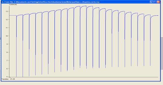
Fig. 1 - Current Profile of an OLTC going through each tap position. The current drop at each tap position change, the Ripple is some 60%.
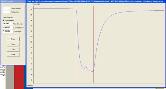
Fig.2 - Transition time between two red cursors shown for a good transition between tap-positions.
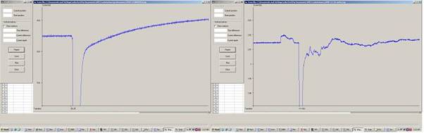
Fig. 3 - Current characteristics for good (left) and badly burned contacts (right)
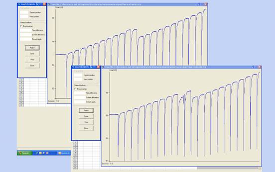
Fig. 4 -Good phase (upper graph) and the defective phase comparison identifying a problem at the neutral
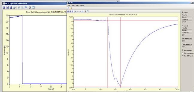
Fig. 5 - Current interruption during transition left – good phase on the right
(This power transformer cleared on Bucholz relay twice before the DRM tests indicated opening during the W phase transition. The diverter was then removed and repaired on site).
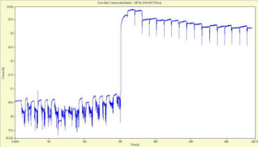
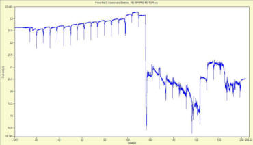
Fig. 6 – Reactance tap changer problem on the raised portion, visible as mirror image of the graphs during tests performed in one direction and the other.
* * *
Contributor:
Ernesto Perez Moreno obtained his M.Sc. Degree in Electrical Industrial
Engineering in 1994. He continued his work on the diagnostics of power
transformers until 1999 when he joined Union Fenosa Distribucion utility as
Head of the Transmission and Distribution Substation Maintenance Department.
Following the merger of Union Fenosa Distribucion Electric with Gas Natural
now known as “Gas Natural Fenosa” Ernesto was appointed Head of Department
in HV Grid Development and Quality Assurance. He has published many articles
and given presentations at National and International Conferences, and is a
member of several CIGRE Working Groups.