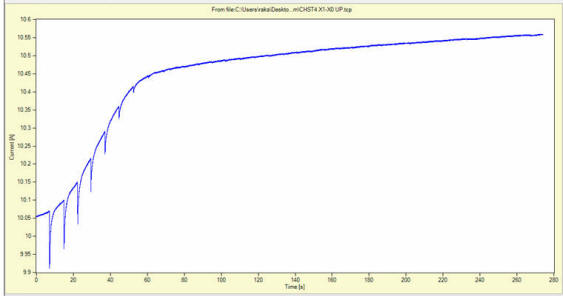
Fig.1. Current stabilization during the test - showing the ripple while change is significant
AMforum Journal 2
Testing transformers equipped with series transformer, or a booster transformer, presents a special case and requires a modified procedure with special algorithm [Journal 1].
There are two transition processes or stabilization periods associated with this construction. As we have two separate circuits, we have two separate currents: a. test current, and b. induced current. The current induced in the series-transformer loop (or regulating circuit) by establishing the test current will die-out following the time constant defined by the R and L parameters of that particular circuit. As these parameters are different for different tap positions, the time constant will change also. This will show as a reflection on the test current stabilization in the main (secondary of the power transformer) winding, and we will observe change in the test current. In conclusion, any change in the test current is indication of current in the series transformer circuit. In fact, once the test current is stable the current in the regulating circuit has died-out, and the winding resistance can be measured without error.
As long as there is a current in the circuit of the series transformer winding, tap changing will create ripples on the test current in the secondary winding.
Fig.1. Current stabilization during the test - showing the ripple while change
is significant
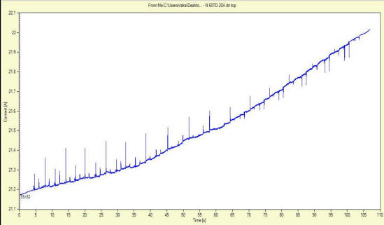
Fig.2. Stabilization was never achieved, but the ripple changed direction with
different tap positions
Contributor
Dr.ing. Raka Levi